
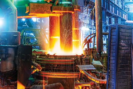
The efficient use of lime and better control of slag chemistry have led to significant energy savings for steelmakers.
Additional benefits include safer and cleaner environments for shops, reduced volumes in lime-to-furnace evacuation systems, better lime yield resulting in less quicklime used during the melting process, and reduced maintenance cost compared to mechanical systems.
In addition, improved injection technology means 100 percent of lime requirements are being delivered directly to the slag, resulting in improved lime utilization, faster dissolution of lime related to increased surface area of lime particles, flexibility in controlling slag characteristics throughout the heat, and improved steel process performance.
The Carmeuse Lime Injection Simulator
The Carmeuse Lime Injection Simulator
Material handling systems have always had an impact on steel plants efficiency of adding lime for precise control of slag chemistry, which led to the growth in EAF steel plants converting to lime injection systems. Once a lime injection system has been installed it is not easy to test without disrupting steel production and therefore it is difficult to address problems before they occur. At Carmeuse, we realized this lack of insight needed to be addressed, and we created a lime injection simulator at our Millersville, Ohio facility to test the limits and interactions of lime with injection systems.
The success of its development depended on its ability to achieve the following important goals:
- Trial various lime injection configurations prior to actual plant installation or modification
- Test and identify where and when potential problems may occur
- Evaluate and collect data to optimize performance levels of the system
- Establish parameters to shorten injection system start-up and tuning


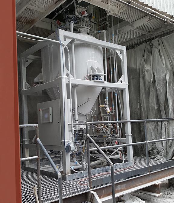
The Carmeuse simulator was originally built to assist a steel plant in the implementation of a new lime injection system. In collaboration with innovative partners in the steel equipment and steel making industries, we were able to reduce the time from start-up to steady-state operation of their new lime injection system. The operational simulator comprised of all relevant components that are typically involved in lime injection systems. This included a truck blow off equipped with a screen box, a feed hopper, an injection vessel, four unique piping configurations and a backpressure simulator to mimic the pressure that an EAF would put on a lime injection system. The screen box was used at the initial loading point of lime from the pneumatic truck to keep oversized materials out of the injection unit, ensuring optimum flow. The ability to then fully customize the configuration of the system allowed us to mimic current and potential lime injection systems to compare and test lime injection materials in multiple configurations. In addition to the multiple configurations possible, Carmeuse also tested a variety quicklime sources and sizes to better understand how each would perform and how the injection equipment should be adjusted accordingly.
An immediate benefit to the simulator is its ability to stress a system in a safe environment as we pushed the simulator beyond typical working limits and conditions to identify where potential issues could arise. During our trials, lime was fed into the silo above the injection pressure vessel via vertical and horizontal piping. The test simulated seven 90-degree elbows at distances ranging from 85 ft. to 263 ft. (49 ft. to 227 ft. horizontal and 36 ft. vertical). This configuration was chosen to model operations for a specific site, however there is flexibility to modify it to simulate a variety of alternative potential layouts.
The unit was continually monitored to ensure that it was operating effectively and efficiently. Throughout the process, lime samples were taken from between the storage bin and the injection pressure vessel to inspect sizing characteristics and ensure consistent gradation for smooth, constant flow.
To ensure the simulator produced the typical pressure generated by an EAF, technicians routinely checked the back-pressure device. This, along with the other critical checks and balances were precisely monitored through the same computer automation that is used in an EAF steel mill. The simulator allowed us to push each evaluation to extreme conditions to determine where system limitations and potential issues may exist.

Key Considerations
Key Considerations
Consistency and control are of paramount importance for lime injection. Key factors to consider are:
- Degradation and segregation of products from lime plant to steel plant
- Different flowability of the injection materials
- Distance from the day bin to the injector, and distance from the silo to the day bin
- The number and angularity of bends in the lime delivery system
- Design of the feeding mechanical system and the path to the injector
- Variability of air pressures throughout the system
- Process control feedback and instrumentation
These variables can present challenges to the consistent control of lime injection. However, they can be mitigated through proper planning and disciplined shop practices. Our extensive testing and refining of lime injection systems continues to allow manufactures to expedite how they are able to overcome these common challenges.
Please click here to download the article.
Image
